
As I mentioned in my last post, I wanted to try some image segmentation! I had a quick go at histogram based segmentation where the largest peak of the histogram was used to find the most occuring pixel (after the colour range was bit crushed) but this didn’t have particularly useful results. This could be used in an application where you want to try and detect a constant background, like these guys were trying to do for single camera robot navigation where the brown floor was their desired segment.
I instead went down the “normal” route of image segmentation based on colour range. This can be as simple as rejecting all pixels that don’t lie within a red, green and blue set of minimum and maximum values though as mentioned here, the RGB colour space mixes pixel intensity with colour i.e. Overall pixel intensity will be the sum of R, G and B (with some weighting depending on whether you want to model it on “human” brightness) meaning that even if you just want to search for “red” objects, the overall pixel intensity will be influenced by the B and G channels, potentially screwing up your algorithms.
This issue can be solved by transforming pixels into another colour space. There are many colour spaces out there to choose from i.e. YCbCr, CMYK, HSV and others. Most applications will stick to YCbCr because its well supported and there is a wealth of information out there about it. You do however need to implement fixed or floating point mathematical operations to convert from RGB to YCbCr – i.e. multiplications by decimal values. To save on resources and keep achievable speed at a maximum, I instead chose the YCgCo colour space. This colour space doesn’t seem as well documented as the YCbCr colour space though it has the massive prime advantage of being implementable with bit shifts and additions only. This massively reduces the logic requirements compared to fractional multiplications.
Once in the YCgCo domain, pixels can be rejected or accepted on whether they fit within a certain minimum and maximum range. By doing this, pixels can be rejected on their colour only, regardless of intensity (to a point). The difference between YCgCo and YCbCr is a full Cb channel translates to full blue intensity whereas a full Cg channel translates to full green intensity.
Results
Implementing this segmentation is reasonably soft on resources (91 logic cells) but the slow model doesn’t actually say it can run at my 96MHz target frequency! This is more a result of my poor coding because pixels are only moved around at 24MHz (12MHz pclk), I juts don’t want to get tangled up in clock domains. If frequency performance becomes an issue, obviously I will start to look into this area more.
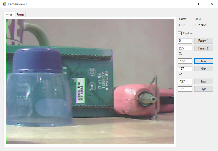 Original image with various coloured objects in the frame (320×240, RGB565)
In the above image, note that the blue cap is partially transparent! This makes segmentation of this object quite a task. Param 1 and Param 2 are Y low and Y high bounds.


Segmentation of red, green and blue objects. Note the transparent cap is present in both the green and blue segments.
As well as segmentation on colour, segmentation of intensity is possible (you can see intensity was left untouched by the Y channel being 0 -> 255, the minimum and maximum possible).


Segmentation of dark and light objects
As the transform used is the YCgCo transform, I wanted to see how it worked with a bright orange bag (thanks Sainsburys!).


Original image of my room and door with the Sainsburys bag at the bottom, then segmented from the image
I could really do with sorting out my Github for this project and adding some comments but that can wait until another time! Hopefully next, I can combine some of these image processing modules to produce something useful.

One thought on “FPGA based OV7670 – Image segmentation”