Preface
SR (switched reluctance) motors are pretty amazing things. Originally developed in 1838, an SR motor uses some of the simplest principles of electromagnetics – energize a coil to create a magnetic field and magnetically permeable materials (i.e. some steels, nickel, iron, cobalt etc) will be attracted to it, similar to how a standard solenoid works. If you instead energize adjacently located coils, you can continuously attract a piece of magnetically soft metal. If these coils are then arranged in a circle and energized sequentially with a piece of magnetically soft metal in the centre – as a rotor, you can create rotation and voila, a switched reluctance motor is born! There are many better explanations than I can give on how a SR motor works so I’ll link one here.
There seems to have been a massive resurgence around SR motors in the past few years with the advent of high density and fast power electronics capable of generating the required switching sequences to drive the motors successfully. Funnily enough, a lot of research was done at my university – the University of Nottingham, especially with developing the power electronics. Since then, SR motors have been used in the Dyson products and the new Tesla model 3.
Why the interest?
I have always been interested in SR motors as some modern day incarnations were developed by many of my lecturers, I remember studying them in multiple modules as well as being examined on the theory and control. It was actually one of the projects during my degree but I didn’t get to do it as I was more electronic focused than electrical. I am now however going into a job where I will be working with SR motors so I feel its something I should get a little acquainted with!
3D printability
SR motors are great because they only need standard easily available elements – Iron, lamination or insulation and copper. The normal way to make a motor is to cut stator cores from electrical steel, laminate them to electrically insulate the large area faces and stack the cores to create the stator. Once stacked, copper wire (generally enamelled) is wound around the poles allowing for the generation of a concentrated magnetic field when current flows through these windings.
If I had a laser cutter, this method would be great but as I no longer live in Nottingham and don’t have access to a laser cutter, I’ve had to devise other methods…
Enter resin casting!
Resin casting
Resin casting is quite a popular hobby thing to do. It consists of making a mold, generally from silicone or plaster and pouring resin (normally an epoxy style resin with an uncured liquid and hardener) into the mold. Once fully cured, the part can be removed from the moldand voila.
I was thinking how I could essentially make my own stators and rotors with the components I have access too i.e. anything cheap off eBay and a 3D printer. The hardest part being that the stator has to be magnetically permeable but also of high electrical resistance to ensure low eddy current losses (this is the reason for the lamination). There does exist iron fill PLA but after having read some reviews and watched a few videos, it doesn’t seem to be particularly magnetically permeable.
I have previously experimented with iron filled silicone (nothing more than very fine atomized iron powder and silicone) to make magnetically permeable silicone, I wondered if this same idea could be extended to resin casting. After a bit of youtubing, it turns out that metal fill resin is quite common for creating realistic metallic looking casts.
Here, metal powder is used in the mould but there are some videos where the powder is mixed into the resin.
With this, I went to Poundland and bought enough Epoxy resin for it to look suspicious…
 That wasn’t even all of the epoxy!
Using a standard polystyrene cup and my iron powder, I whipped up a batch of iron fill epoxy with ratio 1:1:2 (1 part resin, 1 part hardener, 2 parts iron powder) by weight. After mixing and letting it set, I ended up with a solid puck of iron fill epoxy.

My polystyrene cup of iron fill epoxy, this was about 30g or so
To fully see just how magnetically permeable it was, I got my trusty neodymium magnet stack out and gave it a shot.
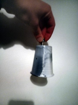
Magnetic adherence!
This was enough to show me that it was at least magnetically permeable. Getting my meter on it gave “infinite” resistance though I’d most likely attribute this to contact resistance between the probes and the resin. I will soon find out the quality of insulation between magnetic particles at a later date but this was enough for me to have a go at casting a stator!
CAD
Having never designed a motor in my life, I decided to run into it head first and get straight into FreeCAD. I checked a few photos out, read a couple of papers and settled on a 6/4 SR motor, 6 poles on the stator, 4 poles on the rotor and got designing.
Stator
I didn’t fancy using much material for this so I made a relatively small stator of size 40x20mm, really small! I really didn’t put much effort into the design as I’m currently learning how to use FEMM to simulate magnetic circuits so there is always the chance of suboptimal design but here was the eventual choice.
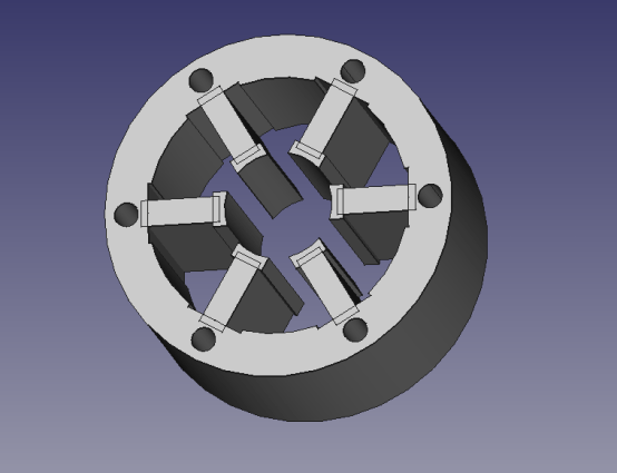
My first attempt at an SR motor stator.
To create a mold for this, I started with a cylinder slightly larger in diameter and subtracted the stator from it.

Subtracted stator mold.
Rotor
For the rotor, I intended to use an off the shelf shaft which consisted of a 50x3mm piece of cylindrical stainless steel rod. I got this from eBay for a pound or two. I would then cast the rotor onto the shaft leaving me with the desired object.

First attempt at my SR rotor, note the salient poles oooh!
Again, by subtracting this from a larger cylinder, I ended up with my mold.

Mold for the rotor
In the above image, the hole for the stainless rod can be seen and the rod will be inserted in here prior to pouring in the resin.
Casing
To hold the motor curing operation, I have also designed some small casing parts which will be printed from standard PLA. These are solely to act as a little stand and to also house the bearings.
 Motor stands
Put it all together and voila!

Full assembly
Molding
As I previously mentioned, molds can be made from either silicone or plaster amongst other materials. unfortunately, I don’t have the ability to make silicone or plaster molds, not forgetting that the epoxy might even bond to these mold materials! What to do here?!
Well I know that modern dual extruder 3d printers have the ability to print water soluble support using PVA filament. Taking this to the extreme and somewhat copying plaster resin molds, why not print the entire mold from this PVA filament?
Enter the PVA molds!

PVA filament mold
As you can see, it didn’t come out too bad! Unfortunately, the vertical cylinders for holes didn’t come out well at all and snapped off at the hint of movement so I will have to drill those in the future but all in all, it wasn’t that bad! I only used a 12% infill and 2 layer wall as this solely has to exist for support purposes and the less PVA used, the less time it will take to dissolve at a later date.

Casting the resin! Note the stainless steel rod in the rotor mold.
One thing of note is that when epoxy cures, it does so exothermically! Its worth noting that this can actually cause the PVA to warp slightly so I had to make sure the molds were kept static during the curing process.
Demolding
During the demolding process, I needed to submerge both molds in water, ensuring the water was changed relatively often to speed up the demolding process. As the water gets saturated with the PVA, it takes longer for the rest of the PVA to dissolve so it is wise to continuously change the water.
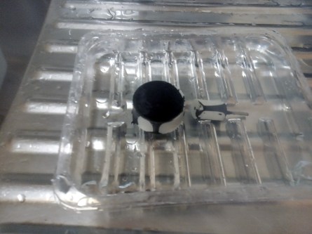
Soaking the parts
As any budding scientist will know however, placing iron in water causes it to rust! I didn’t see any major signs of this until after the entire demolding process so for future metal fill powders, I may use magnetite instead though this will be something I need to experiment with.
Results
For my first ever attempt of casting, moreso using cheap epoxy and iron powder, I’m actually quite impressed at the outcome. My stator has turned out pretty good though in need of a bit of touching up – I’ve ordered some files so once they arrive, I will do the touchups. The rotor unfortunately didn’t turn out that great because there was some air present in the mold so this will need to be redone. The rotor was also a little bit too large and didn’t fully fit into the stator so this will need to be remolded anyway.

Molded outputs
And so voila! Successfully molded parts using cheap poundland epoxy, iron powder and PVA molds. The next step will be to remold the rotor, print the motor mounts, drill the stator, wind the stator and assemble the entire thing!
Electronics
The main issue with the uptake of SR motors has been the issue of control. SR motors generally require good positional feedback of the rotor angle to ensure the poles are turned on at the correct moments, allowing for a positive torque and therefore rotation of the rotor. This can generally be achieved with an optical encoder or other methods. There are however modern methods which can predict the rotor position sensorlessly, like with a BLDC motor. An SR motor generates no back EMF so the rotor position cannot be sensed as a zero crossing on an unconnected phase winding. An SR motor however has a continuously varying inductance with rotor position. From this, the current rotor position can be inferred. It is worth noting however that inductance also varies with current so this isn’t a completely simple task and will generally require interpolating between a current table and a “current slope” result to provide an estimate of rotor position.
For the control of this version however, I will be printing an optical encoder style wheel so I can detect the position of the rotor. I realistically need an absolute encoder so I can see the exact position of the rotor and therefore be able to start it without external assistance, I may however to start with just use a single opto detector and initially spin it by hand.
From a power electronics perspective, I will be powering the motor from 5V (as per usual…) and use the standard totem pole drive system. More to come on this later!

Cool stuff! looking forward to a part II.