For once, I have actually decided to be proactive regards to actually writing software (shock horror!). I decided as I’m going to be using a PI for this project, I should probably learn Python finally. It also gave me a good reason to figure using FEA within FreeCAD, something I’ve been meaning to do for a while!
Kinematics
The first step I decided to take was a 2D simulation of the arm constrained in the XY plane. I wrote this in Python using Numpy and Matplot lib and this gave me the opportunity to visualize the operational envelope of the arm in 2D.

Sparse arm operating envelope

Denser operating envelope

GIF of all end effector positions
To get the above GIF, I assumed the bending could be represented by a bezier curve. By plotting the position of the end effector (tip of the black bone), I can get the operating envelope images above.
Obviously this method is acceptable for a 2d representation but for an arm that’s going to operate in 3D, its a little limited.
Cue the 3D version written literally today.

3D version of the arm simulator
This again is written using python and matplotlib. In this version, to save the derivation of the inverse kinematics, I’ve been doing a monte carlo-esque simulation and using a numerical optimization technique to try and find the best joint angles within a constrained range to reach said point with minimal error, this produces some really interesting results. The blue dot represents the base and the green dot represents the end effector. This version assumes one bone is actually the length of two which is only done to make the simulation easier to write.

Trying to reach all points on a line along the X axis
The optimization is surprisingly effective at this. I’m using the standard numpy minimization optimization and the euclidean distance between predicted position and target position as my cost function. Across 100 random positions with a optimization tolerance of 0.0001, 83% of all randomly selected positions could be resolved with an accuracy of 2mm. Average time for an optimization was ~115ms. To get fluid motion planning on the real thing, I’ll need to get this down to around 20ms and incorporate something that preferably takes the last known position to stop the arm jumping around randomly. It is worth mentioning optimization takes this long on an i7-7700HQ so it doesn’t fill me with much hope for the pi…
PI Software
I’ve decided to make the actual tentacle interface platform independent. For this, I have an STM32 controlling all 12 servos whilst also taking bend feedback along with other interfaces (I2C, UART etc.) if required. The STM32 is connected to the host through USB and acts as a standard CDC device. This allows me to use any device as the host. I’m currently going to be using a Pi 3b though I’m looking to upgrade this to a Jetson nano depending on the real time performance.
For the actual computer vision and “intelligence” part, I’ve got two 640×480 usb webcams which I’m reading with OpenCV. Each frame is then sent to a YOLO CNN and objects are detected. The eventual aim is to incorporate the outputs of these CNNs with some visual servoing and speech recognition to decide which objects to track – I’m not yet however at this point!
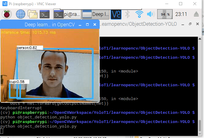
Pi + USB webcam + yolo = object detection
FEA
I’ve been using FreeCAD for all of my work and I can truly say its a really good piece of software given its free. I’ve recently learned that you can use it for FEA simulations which adds another depth to its capabilities. I can use this to see how the bones will bend when tension is applied.

This simulation however is somewhat arbritrary as I didn’t now the material properties for 3d printed TPU. This instead just uses material properties for standard TPU.
Stay tuned for further updates!
