So I’ve finally got round to writing my first tutorial!
This first tutorial will be on using the STM32F0 with simple GPIO ports. I’ve set it up so that the LED’s will alternate depending on whether the push button is pressed or not. I’m using Coocox for my IDE and there are loads of other tutorials on the net on how to install this! I will however include information on how to create a project. This is also my first time using Github so if something is a bit dodgy, go easy on me!
If you’ve just decided to download my project from my Github, you can ignore the section below on creating a project.
Project creation:
To start with, you need to create a project in coocox. From the starting screen, select “Create a New Project”

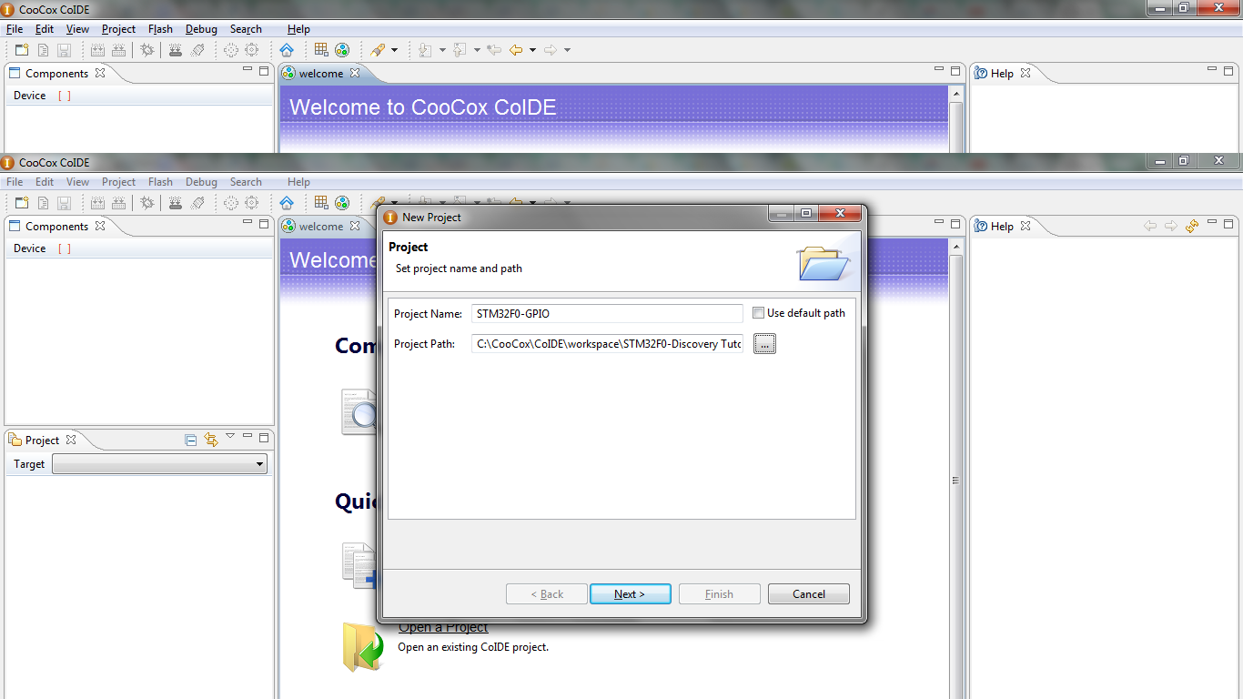
Once this has been clicked, a new screen will come up asking for a project name and project path. I’ve selected my Github repository folder for my “Project Path” and named the file STM32F0-GPIO for the “Project Name” (kind of self explanatory!). Once you’ve done this, click “Next >“.
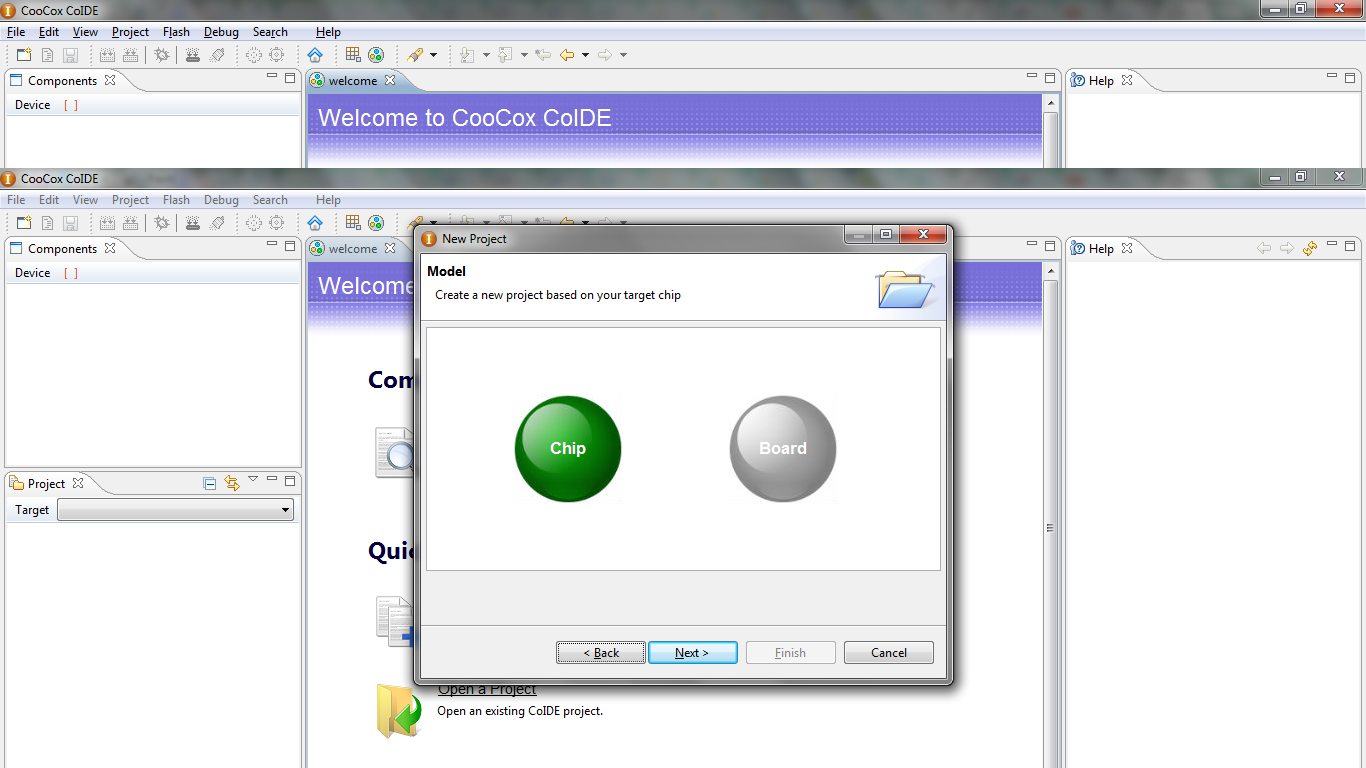
Now the project has been named, you will have to choose your processor. Firstly, select “Chip” then click “Next >“.
You can find out what chip is used on the STM32F0 Discovery PDF document (http://goo.gl/8dsPTZ). For ease of this tutorial, the chip is the “STM32F051R8“.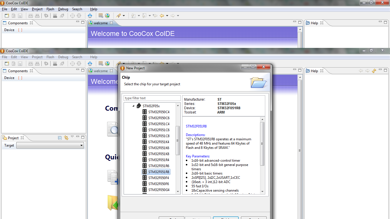
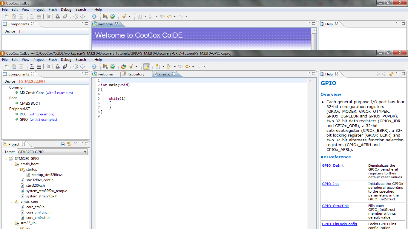
Now that the basic project parameters have been set, its time to include the libraries required for this simple application. Nearly all useful applications will need to include “RCC” as this allows clocks to be routed to peripherals. By clicking directly on the RCC library, Coocox automatically includes “M0 Cmsis Core” and “CMSIS BOOT“, both of which are vital to the function of the microcontroller.
As well as the RCC library, you will want to include the “GPIO” library.
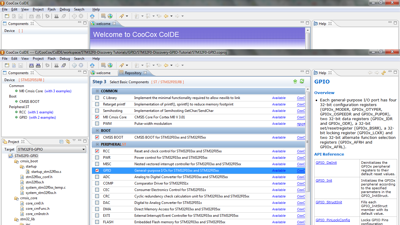
Wahoo! If you’ve made it this far, you’re ready to start coding! If you now double click on “main.c” in the bottom left box at the bottom, you should arrive at a screen like so.
GPIO Initialization
The first step to GPIO Initialization is enabling the clocks to the GPIO peripherals. Without the clocks being sent to the GPIO’s, nothing will happen when you try and use them! To enable the clocks, you need to use the RCC_AHBPeriphClockCmd function. If you read through the STM32F051R8 datasheet, it will state what peripheral is on which clock tree. The STM32F0 series has three clock trees, notably AHB, APB1 and APB2. For the STM32F0 series, the GPIO will always be attached to the AHB bus. Enabling the clocks is slightly less portable and requires you knowing which GPIO’s you will be using. As I’ll be using both GPIOA and GPIOC, I need to enable clocks for both using the below piece of code:
RCC_AHBPeriphClockCmd(RCC_AHBPeriph_GPIOA, ENABLE);
RCC_AHBPeriphClockCmd(RCC_AHBPeriph_GPIOC, ENABLE);
When I code for an application, I like to define most of the constant parameters are the start of the program. This increases program portability and allows for easy changes in the future. In this program, I’ve defined the LED pins (Green LED and Blue LED), the LED GPIO’s, the Push Button pin and the Push Button GPIO. This makes it easier in the future if any of these pins need to be changed from the initial values without trawling through the code and changing them individually. You will also need to define the structs for the GPIO using GPIO_InitTypeDef. Structs are really cool! They are essentially a table of values. The GPIO_InitTypeDef struct contains 5 entries:
- GPIO_Pin
- GPIO_Mode
- GPIO_OType
- GPIO_PuPd
- GPIO_Speed
For each of these entries, you can assign a value. For example, we know that we need to tell the struct what GPIO pins we’ll be using for the LED’s so the LED pins can be assigned to the GPIO_Pin entry.
Before you can enter values into a struct however, you need to create a version of that struct with your own name. To do this in CooCox, its as simple as writing:
GPIO_InitTypeDef Gp;
All the above line of code means is: “I want to create a GPIO_InitTypeDef struct called Gp.”
Now that I’ve created that struct, I can start assigning values. As with the above example, I can assign the GPIO_Pin values like so:
Gp.GPIO_Pin = GreenLED_Pin | BlueLED_Pin;
In this context, the Pin values can be Or’d as both the green and blue LED’s are on the same GPIO (GPIOC, pin 8 and 9).
Now that I’ve defined the GPIO pins, I need to tell the struct how I want these pins to be configured.
Firstly, I’ve decided to tell the struct that these pins are going to be outputs. The struct entry GPIO_Mode allows me to configure the data direction of these pins. The line of code to do this is:
Gp.GPIO_Mode = GPIO_Mode_OUT;
There are many different GPIO Modes that can be selected. These are: GPIO_Mode_OUT (Setting pins as digital outputs), GPIO_Mode_IN (Setting pins as digital inputs), GPIO_Mode_AN (Setting pins as analog inputs) and finally GPIO_Mode_AF (Assigning pins to internal peripherals such as the SPI device).
Now that the data direction has been assigned, the output type of this pin can be set using the struct entry GPIO_OType. The outputs of an STM32F0 chip can be either Open Drain or Push Pull, in code terms, the two parameters are GPIO_OType_PP (push pull) and GPIO_OType_OD (open drain). Open Drain is a sometimes useful configuration as it allows outputs to be easily OR’d together. To achieve the push pull output that we require to drive the LED’s, the code looks like:
Gp.GPIO_OType = GPIO_OType_PP;
The next parameter that I’ve declared is the input pull ups using the struct entry GPIO_PuPd. As these pins that I’m currently defining are push pull outputs, its not really necessary to fill in this parameter, however for completeness, I will. With the STM32 IC’s, you can define an internal pull up resistor (GPIO_PuPd_UP), pull down resistor (GPIO_PuPd_DOWN) or no resistor at all (GPIO_PuPd_NOPULL). As I don’t want any pull up/down resistors at all, my line of code for this looks like:
Gp.GPIO_PuPd = GPIO_PuPd_NOPULL;
The final parameter for the GPIO struct is the GPIO Speed. This struct entry is GPIO_Speed. There are many advantages to not selecting the fastest speed for the GPIO unless its required. The main one of these is reduced power and EMI. As I’m only going to be driving LED’s fast enough for the eye to see, I’m going to set this to the slowest one. The STM32F0 series of chips have 3 different defined speeds: 2MHz (GPIO_Speed_Level_1), 10MHz (GPIO_Speed_Level_2) and finally 50MHz (GPIO_Speed_Level_3). For my application, i’m going to use GPIO_Speed_Level_1. My code looks like so:
Gp.GPIO_Speed = GPIO_Speed_Level_1;
Now that this struct has been completely filled, I can assign these values to the LED GPIO (GPIOC) using the nice function GPIO_Init. This function requires the GPIOA you’re assigning to, along with a pointer to your struct containing the values you wish to assign. For me, this piece of code looks like:
GPIO_Init(LED_GPIO, &Gp);
All that is required after this is setting the push button as an input. Realistically, only one line needs to be changed and that is the one containing GPIO_Mode. As I want the push button to be an input, I change this line from:
Gp.GPIO_Mode = GPIO_Mode_OUT;
to:
Gp.GPIO_Mode = GPIO_Mode_IN;
and reassign the GPIO struct to the correct GPIO:
GPIO_Init(PushButton_GPIO, &Gp);
To ensure that the preconfigured pins aren’t lost when a new struct is assigned, the function GPIO_Init or’s the values, keeping previous configurations.
The final code for the whole GPIO Initialization looks like:
//Enable clocks to both GPIOA (push button) and GPIOC (output LEDs)
RCC_AHBPeriphClockCmd(RCC_AHBPeriph_GPIOA, ENABLE);
RCC_AHBPeriphClockCmd(RCC_AHBPeriph_GPIOC, ENABLE);
Gp.GPIO_Pin = GreenLED_Pin | BlueLED_Pin; //Set pins inside the struct
Gp.GPIO_Mode = GPIO_Mode_OUT; //Set GPIO pins as output
Gp.GPIO_OType = GPIO_OType_PP; //Ensure output is push-pull vs open drain
Gp.GPIO_PuPd = GPIO_PuPd_NOPULL; //No internal pullup resistors required
Gp.GPIO_Speed = GPIO_Speed_Level_1; //Set GPIO speed to lowest
GPIO_Init(LED_GPIO, &Gp); //Assign struct to LED_GPIO
Gp.GPIO_Pin = PushButton_Pin; //Set pins inside the struct
Gp.GPIO_Mode = GPIO_Mode_IN; //Set GPIO pins as output
Gp.GPIO_PuPd = GPIO_PuPd_NOPULL; //No pullup required as pullup is external
GPIO_Init(PushButton_GPIO, &Gp); //Assign struct to LED_GPIO [Edit:] //Assign struct to PushButton_GPIO
GPIO access functions:
Obviously, now you’ve initialized your GPIO’s, you’re going to want to use them! Firstly, to read a GPIO pin, you will want to use the function GPIO_ReadInputDataBit. This function takes the GPIO and GPIO pin that you want to read and will return a value whether the pin is set or not. In my piece of code, I want to use this value to toggle the LED’s so I’ve assigned it to a standard unsigned 8bit integer using the below piece of code:
ButtonRead = GPIO_ReadInputDataBit(PushButton_GPIO, PushButton_Pin);
Now that I’ve got the value of that button stored in a variable, I can use that to toggle the LED output pins. The two standard functions for setting or resetting a GPIO bit are GPIO_SetBits and GPIO_ResetBits. When the button is not pressed, I want the blue LED to be on and the green LED to be off. Once the button is pressed, I want the blue LED to be off and the green LED to be on. Using an if/else statement and the two above functions, I can achieve the above in this piece of code:
if(ButtonRead){ //If button is pressed, turn green LED on and blue off
GPIO_SetBits(LED_GPIO, GreenLED_Pin);
GPIO_ResetBits(LED_GPIO, BlueLED_Pin);
}
else{ //If button isn’t pressed, turn green LED off and blue on
GPIO_ResetBits(LED_GPIO, GreenLED_Pin);
GPIO_SetBits(LED_GPIO, BlueLED_Pin);
}
And thats it! For this simple program, that will allow you to toggle between the two LED’s.


The final code is:
#include <stm32f0xx_gpio.h>
#include <stm32f0xx_rcc.h>
GPIO_InitTypeDef Gp; //Create GPIO struct
//Define LED pins
#define GreenLED_Pin GPIO_Pin_9
#define BlueLED_Pin GPIO_Pin_8
#define LED_GPIO GPIOC
//Define Push button
#define PushButton_Pin GPIO_Pin_0
#define PushButton_GPIO GPIOA
int main(void)
{
//Enable clocks to both GPIOA (push button) and GPIOC (output LEDs)
RCC_AHBPeriphClockCmd(RCC_AHBPeriph_GPIOA, ENABLE);
RCC_AHBPeriphClockCmd(RCC_AHBPeriph_GPIOC, ENABLE);
Gp.GPIO_Pin = GreenLED_Pin | BlueLED_Pin; //Set pins inside the struct
Gp.GPIO_Mode = GPIO_Mode_OUT; //Set GPIO pins as output
Gp.GPIO_OType = GPIO_OType_PP; //Ensure output is push-pull vs open drain
Gp.GPIO_PuPd = GPIO_PuPd_NOPULL; //No internal pullup resistors required
Gp.GPIO_Speed = GPIO_Speed_Level_1; //Set GPIO speed to lowest
GPIO_Init(LED_GPIO, &Gp); //Assign struct to LED_GPIO
Gp.GPIO_Pin = PushButton_Pin; //Set pins inside the struct
Gp.GPIO_Mode = GPIO_Mode_IN; //Set GPIO pins as output
Gp.GPIO_PuPd = GPIO_PuPd_NOPULL; //No pullup required as pullup is external
GPIO_Init(PushButton_GPIO, &Gp); //Assign struct to LED_GPIO
uint8_t ButtonRead = 0; //Initialize ButtonRead variable
while(1) //Infinite loop!
{
//Read button input
ButtonRead = GPIO_ReadInputDataBit(PushButton_GPIO, PushButton_Pin);
if(ButtonRead){ //If button is pressed, turn green LED on and blue off
GPIO_SetBits(LED_GPIO, GreenLED_Pin);
GPIO_ResetBits(LED_GPIO, BlueLED_Pin);
}
else{ //If button isn’t pressed, turn green LED off and blue on
GPIO_ResetBits(LED_GPIO, GreenLED_Pin);
GPIO_SetBits(LED_GPIO, BlueLED_Pin);
}
}
}
I’ll be considering GPIO AN and AF modes in further tutorials where they apply.
The project is on my github at: https://github.com/pyrohaz/STM32F0-Discovery-GPIO-Tutorial
I hope you’ve found this tutorial useful and I’ll be doing more in the future!

Great tutorial, really helpful for me! Keep up the good work, sir!
One minor correction, though: GPIO_Init(PushButton_GPIO, &Gp); //Assign struct to LED_GPIO -> comment should be “Assign struct to PushButton_GPIO ” 😉
Too true! i’ll make that correction now, thanks!
No problem. BTW, do you have any suggestions where and how to find any good not-too-complex FreeRTOS examples (code)? You see, I’m currently studying FreeRTOS and don’t know how to start. (I’m using STM32F0 discovery board kit). Thanks in advance!
I’m afraid not, the only RTOS I’ve used is the one that comes free with Coocox, CoOS. If it isn’t vital that you use FreeRTOS, i’d definitely recommend having a look at CoOS, its free too!
hy, do you know how to access eeprom stm32f051?
Excellent