
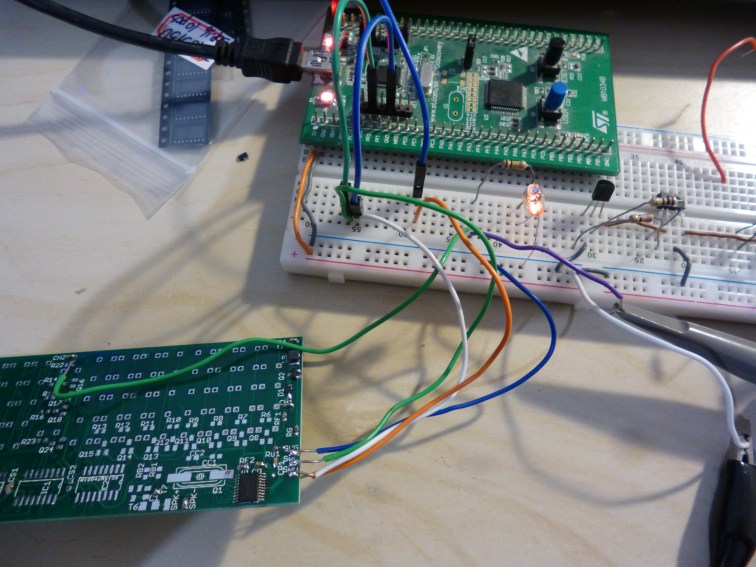
Today, my PCBs arrived, wahoo! Therefore I’ve been able to have a quick go at making my neon clock. I tested it in parts to make sure each section worked before putting it completely together. Unfortunately, my high voltage PNP transistors haven’t arrived yet so I’m currently testing it with TO92 transistors in their place.
Testing the boost converter with a single neon bulb – success!
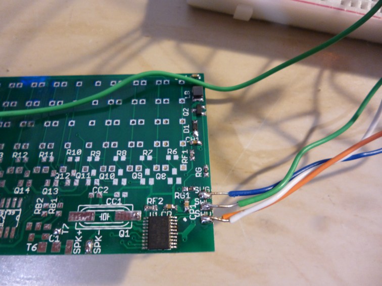
The boost converter section itself is tiny! You can see the inductor in the top right corner.
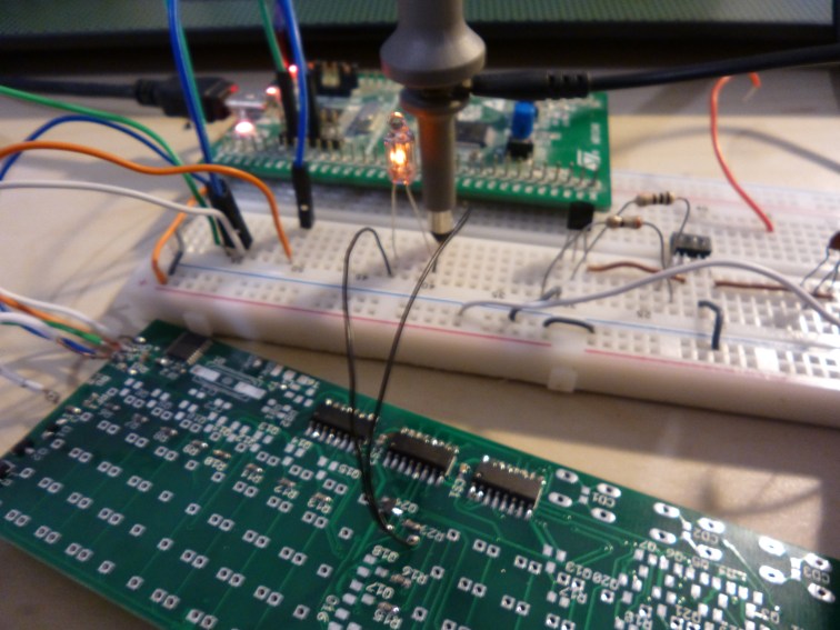
The next step was testing the neon bulb with low side switching (this is for the middle colon) – success!
One issue so far however is the temperature of the boost converter. It is notably warmer than the rest of the PCB and while it is just bearable to touch, its probably not doing any of the components particularly well. I’m also needing to run it at way too high of a frequency for the MOSFET and diode to be able to switch at – considering there is no dedicated MOSFET driver, 350kHz!
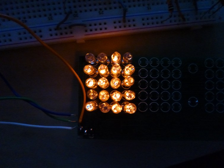 The first segment! As you can see, not all the bulbs are properly working yet.
Having populated one of the dot matrix segments, my fears of the neons not turning off properly was somewhat true. Some of the neons would flicker a bit and others would not. In the image above, I’m scanning the rows one by one (1ms delay between row) but some of the bulbs just aren’t lighting. I’m not too sure if this is because the strike voltage is too low or whether they’ve been damaged in soldering.
I’m going to continue the rest of the build tomorrow…
